
Before we start i am going to tell you about this post,
Firstly i"ll show you the things yo need to know to design your own SCADA using a Omron PLC.
I am also attaching some sample project which you can modify using VB.Net.
https://automationsolutionz.blogspot.com/p/visual-studio-with-plc.html
The FINS communications service
enables client control of operations such as
reading or writing server PC memory
area data without the need to program
these operations into the server PC
user program. The Ethernet Unit uses a dedicated
UDP/IP port to execute the FINS
communications service.
The FINS communications service is
carried out through the exchange of FINS
command frames and their corresponding
response frames. (There are also
commands with no responses.)
Both command frames and response
frames are comprised of a FINS header
for storing transfer control
information, a FINS command field for storing a command,
and a FINS parameter/data field for
storing command parameters and
transmission/response data. Before you start, you need to understand the frame and syntax of the command and response you will get from that command.

Here below you can see the fins SEND Command frame

In response to the SEND frame you will receive a response code.
The response code (one byte each for
MRES and SRES) for the command is
added at the
beginning of the FINS parameter/data field in the response frame

Now lets see in detail.

RSV (Reserved by system)
Set to 00 (Hex).
GCT (Permissible Number of Gateways)
Set to 02 (Hex).
DNA (Destination Network Address)
Specifies the number of the network where the destination node is located.
00 (Hex): Local network
01 to 7F (Hex): Destination network number (1 to 127)
DA1 (Destination Node Address)
Specifies the number of the node where the command is being sent. This
node number is the address used for FINS, and is different from the IP address
used for Ethernet.
00 (Hex): Local PC Unit
01 to 7E (Hex): Destination node number (1 to 126)
FF (Hex): Broadcasting
When multiple Communications Units are mounted, DA1 specifies the node
number of the Unit connected to the network specified by DNA.
DA2 (Destination Unit Address)
Specifies the number of the Unit at the destination node.
00 (Hex): PC (CPU Unit)
10 to 1F (Hex): CPU Bus Unit #0 to #15 (16 to 31)
E1 (Hex): Inner Board
FE (Hex): Unit connected to network.
SNA (Source Network Address)
Specifies the number of the network where the source node is located.
00 (Hex): Local network
01 to 7F (Hex): Source network number (1 to 127)
SA1 (Source Node Address)
Specifies the local node number. The ranges of numbers that can be specified
are the same as for DA1.
SA2 (Source Node Address)
Specifies the number of the Unit at the source node. The ranges of numbers that
can be specified are the same as for DA2.
SID (Service ID)
The SID is used to identify the process that data is sent from. Set any desired
number from 00 to FF for the SID. The same number will be returned in the response,
allowing you to match commands and responses in your application.

This is the memory code table

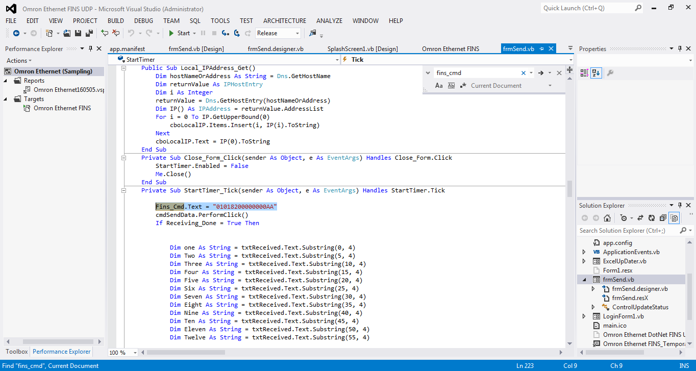
In the below mentioned image you can see i have a tag named Fins_Cmd_Text = "010230000A00000101"
1) Here 0102 defines Memory Area Write, Where MR= 01 and SR= 02 ("010230000A00000101")
2) 3000 is variable type mentioned in above image is for CIO. ("010230000A00000101")
3) 000A00 is the Beginning address.("010230000A00000101")
4) 0001 is the number of elements.("010230000A00000101")
Now we just need to implement the above data to the Command Syntax
Now we just need to implement the above data to the Command Syntax

RemoteIPAddress.Text = "192.168.250.1"
ICF = "80"
GCT = "03"
RSV = "00"
SID = "00"
SNA1.Text = "00" 'SNA$"
SA11.Text = "64" 'SA1$
SA21.Text = "00" 'SA2$
DNA1.Text = "00" 'DNA$
DA11.Text = "00" 'DA1$
DA21.Text = "00" 'DA2$


Download Sample: https://automationsolutionz.blogspot.com/p/visual-studio-with-plc.html
can share program please?
ReplyDeletehello can i get the code
ReplyDelete