Mitsubishi VFD A700 Profibus communication with Q-PLC (QJ71PB92V)
FR-A7NP Profibus Option unit
System configuration

*The stations (61) DP-salves can be increased by using 1 repeater in the segment.
* When using 125 DP-Slaves 3 no of repeaters should be used.
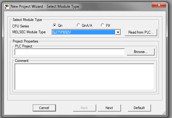
Profibus Card QJ71PB92V


Wiring

Wiring Termination for bus terminator :
When the QJ71PB92V is a terminal station, use a connector with built in bus terminator
that meets the following wiring specification :

Transmission distance

Master Configuration


Slave Setting


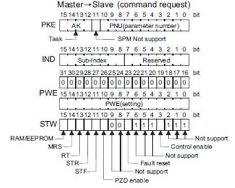
PPO Types
The option unit operates as a "slave of the Profibus DP master" or a "controller equivalent to Profibus DP
master class 1 on an RS-485 network".
The Profibus profile (data buffer) can be selected from among six different types, "PPO type1" to "PPO type5", "A5NP". Module type is changed with the slave module setting. For details, refer to the instruction manual of the Network Master Configuration Software. The configuration of PPO type is as follows :

Buffer memory Configuration
As per PPO type 1(D1000~D1005 will be used for Command response)
And (D2000~D2005 will be used for Command request)


The option unit operates as a "slave of the Profibus DP master
Sample Ladder Programming

DP Module is installed in order from Slot 0 as shown in the previous figure, and the following start I/O No’s are to be set in the GX Developer --> PLC parameter


Settings :
a) QJ71PB92V

b) DP-Slave Setting :

Programming Example : Start/Stop

Frequency Command
The frequency can be given by either given the value in define register or by given RH, RM, RL command.

As per PPO Type 1 we cannot use ECW functions, for using ECW commands we need to select the PPO type 2, 4 or 5

Programming Example : Parameter Read/Write
You can use the PNU to make parameter setting from the network.
The table shown below lists the PNU numbers corresponding to the parameter settings.

For Example : To read/Write the value in Pr.1 we need to use PNU “P1001”

To Read the value from PNU “P1001” (Pr.1: Max. Freq.) we also need to understand the buffer memory details


Which version gx works 2 supports gx configurator dp.
ReplyDelete